
« Reverse proxy with HTML rewriting using Apache | Home | Disable dragging of an element in JSXGraph »
Reverse engineering the Fischertechnik blinker
By admin | July 13, 2014
The Fischertechnik blinker comes in a enclosed case with no other sensory inputs with two wires, a yellow wire and a blue wire.
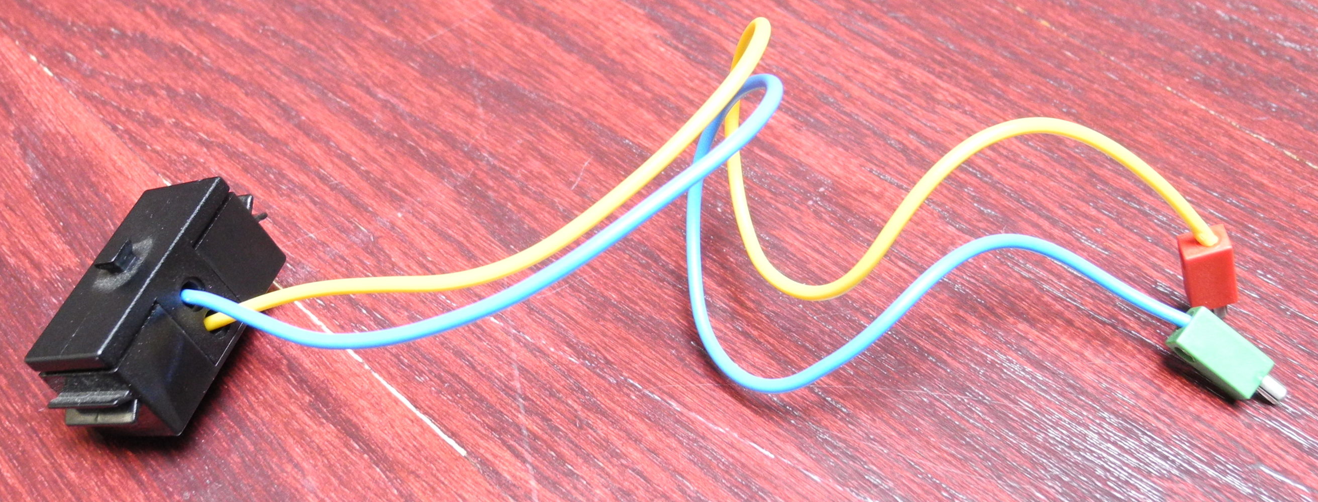
The Fischertechnik blinker
As such, I reverse engineered the Fischertechnik blinker to understand how it works through desoldering, a camera, and a lot of drawing on the GIMP.
It turns out that the blinker is intended to be used like a switch in a series circuit before a load, with the yellow lead being the positive end and the blue lead being the negative end.
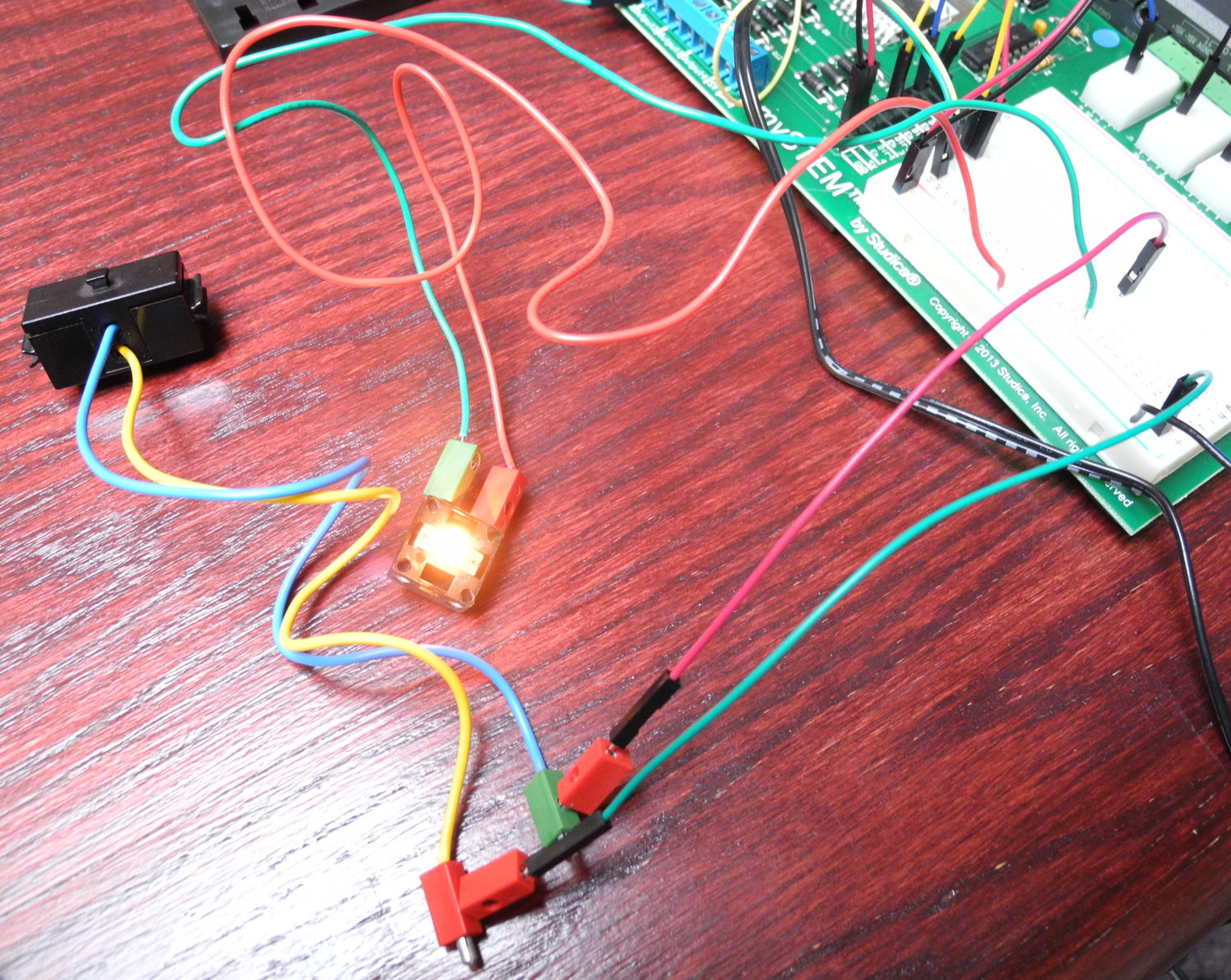
Series circuit with FT blinker on mySTEM board
The main idea here is that the board uses a 555 timer (555C EZ606 with STMicroelectronics logo, surface-mounted) with fixed frequency (fixed R1, R2 and C) in astable mode to control a BSP 75N MOSFET transistor.
The power supply for the ICs is controlled in parallel with a diode and a 470Ω resistor to protect the ICs, while the MOSFET controls the connection to the other lead.
It features an unknown-model fuse (VW UG4 GP613) on the emitter of the transistor, presumably to protect the circuit from excess.
A diode and 100 µF capacitor cap are present, possibly to smooth out the power input for the ICs during temporary dislocations. Considering that it is a Fischertechnik component, its purpose is probably to ensure continued reliability when it is handled roughly, shaken, and dropped by students.
After complete disassembly:
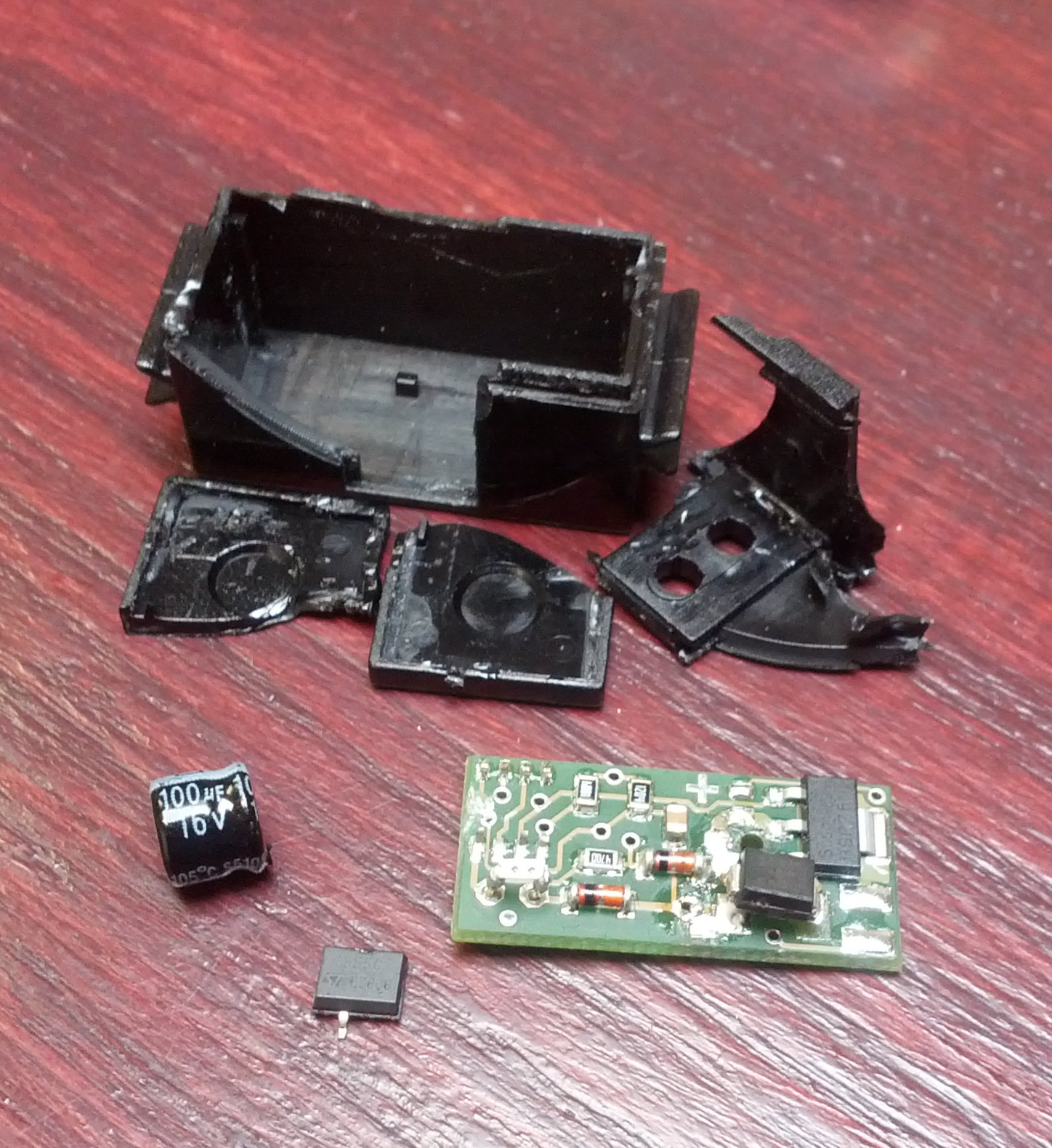
Fischertechnik blinker, disassembled
With traces and PCB features:
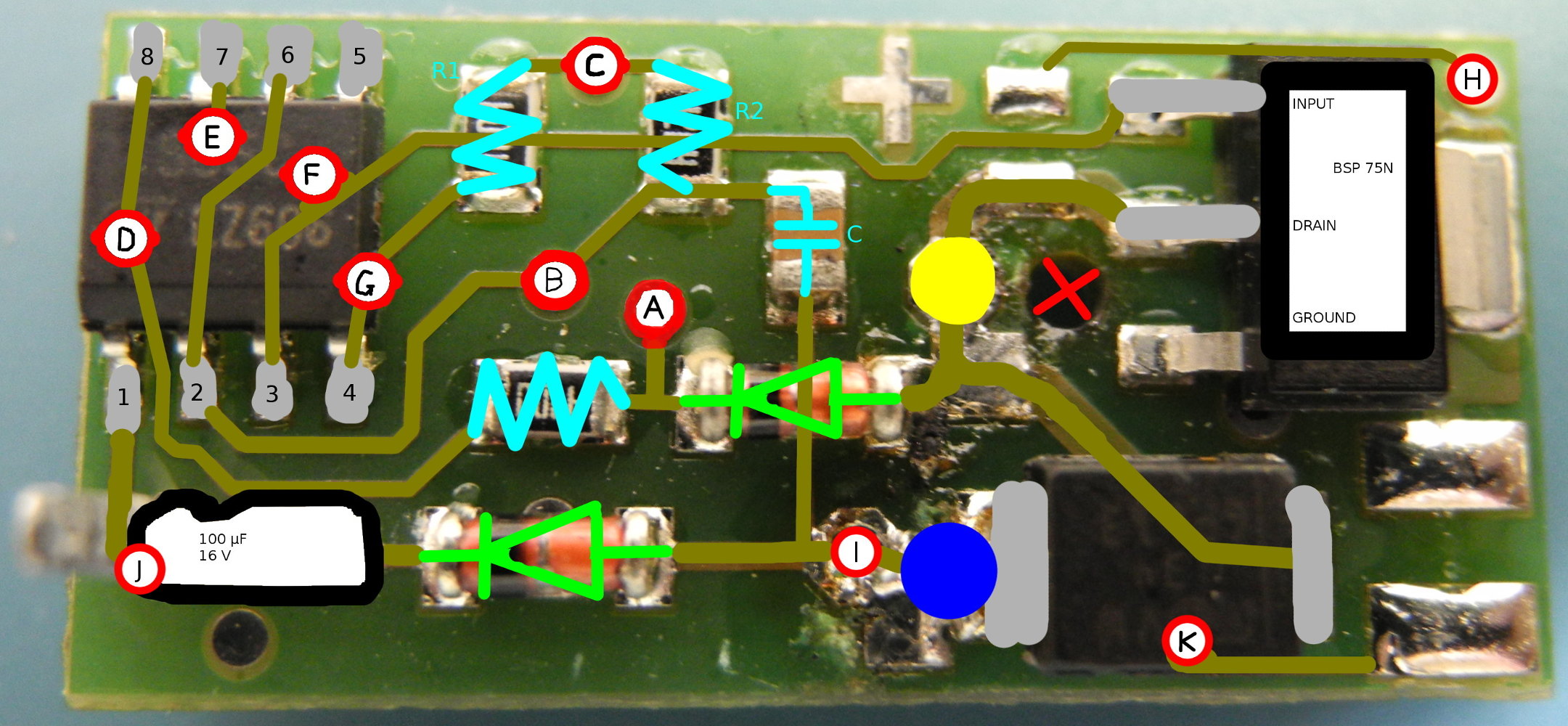
Front view, with traces and PCB features
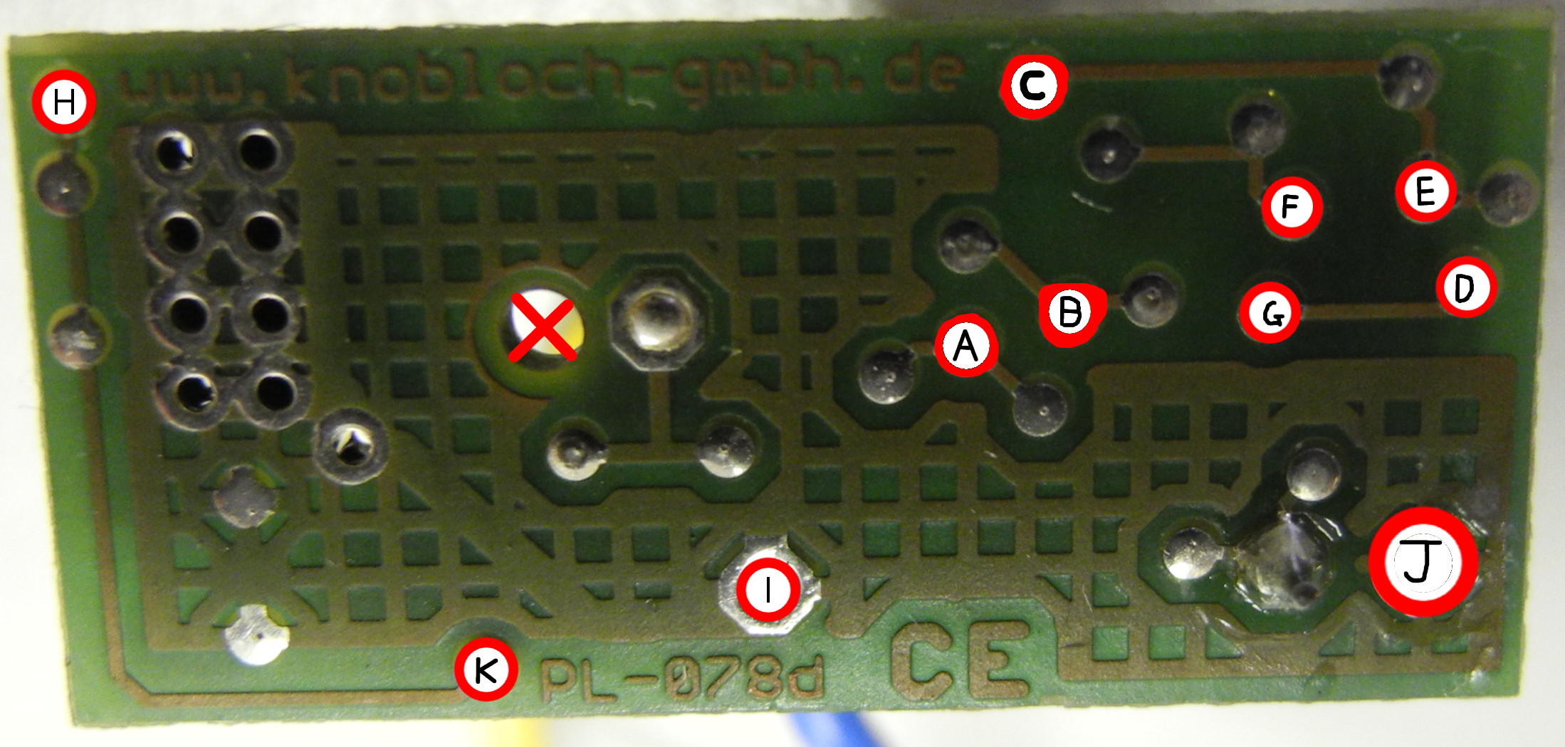
Back view, with traces and PCB features
Schematic:
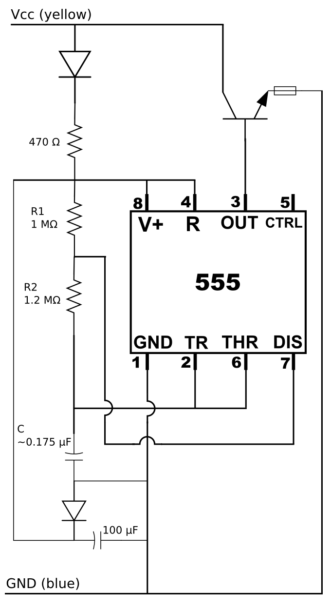
Fischertechnik blinker schematic
Since C is a generic-looking ceramic capacitor with no markings, its capacitance was estimated by using the period.
The light was measured to blink 100 times in 41.21 seconds, giving:
$$
T = 0.4121 \text{s} \\
f = 2.426 \text{s}^{-1}
$$
Given R1 = 1 MΩ and R2 = 1.2 MΩ from above and f = 2.426, we can calculate C using the following equation:
$$
f = \dfrac{1}{\ln 2 * C * (R_1 + 2*R_2)}
$$
C then works out to about 0.175 µF.
If you found this article helpful or interesting, please help Compdigitec spread the word. Don’t forget to subscribe to Compdigitec Labs for more useful and interesting articles!
Topics: Electronics | 40 Comments »
August 1st, 2025 at 04:39
… [Trackback]
[…] Here you can find 56750 additional Information on that Topic: compdigitec.com/labs/2014/07/13/reverse-engineering-the-fischertechnik-blinker/ […]
August 4th, 2025 at 19:43
… [Trackback]
[…] Info to that Topic: compdigitec.com/labs/2014/07/13/reverse-engineering-the-fischertechnik-blinker/ […]
August 4th, 2025 at 21:44
… [Trackback]
[…] Information on that Topic: compdigitec.com/labs/2014/07/13/reverse-engineering-the-fischertechnik-blinker/ […]
August 6th, 2025 at 21:46
… [Trackback]
[…] Information on that Topic: compdigitec.com/labs/2014/07/13/reverse-engineering-the-fischertechnik-blinker/ […]
August 8th, 2025 at 19:10
… [Trackback]
[…] There you can find 1565 additional Info on that Topic: compdigitec.com/labs/2014/07/13/reverse-engineering-the-fischertechnik-blinker/ […]
August 9th, 2025 at 18:08
… [Trackback]
[…] Here you will find 43237 more Info on that Topic: compdigitec.com/labs/2014/07/13/reverse-engineering-the-fischertechnik-blinker/ […]
August 9th, 2025 at 22:49
… [Trackback]
[…] Find More to that Topic: compdigitec.com/labs/2014/07/13/reverse-engineering-the-fischertechnik-blinker/ […]
August 14th, 2025 at 18:27
… [Trackback]
[…] Read More Info here to that Topic: compdigitec.com/labs/2014/07/13/reverse-engineering-the-fischertechnik-blinker/ […]
August 18th, 2025 at 19:44
… [Trackback]
[…] Read More on to that Topic: compdigitec.com/labs/2014/07/13/reverse-engineering-the-fischertechnik-blinker/ […]
September 10th, 2025 at 20:05
… [Trackback]
[…] Find More on to that Topic: compdigitec.com/labs/2014/07/13/reverse-engineering-the-fischertechnik-blinker/ […]
October 9th, 2025 at 22:53
… [Trackback]
[…] Read More Information here to that Topic: compdigitec.com/labs/2014/07/13/reverse-engineering-the-fischertechnik-blinker/ […]
October 14th, 2025 at 12:49
… [Trackback]
[…] Find More on that Topic: compdigitec.com/labs/2014/07/13/reverse-engineering-the-fischertechnik-blinker/ […]
October 14th, 2025 at 18:43
… [Trackback]
[…] Here you will find 76116 more Info on that Topic: compdigitec.com/labs/2014/07/13/reverse-engineering-the-fischertechnik-blinker/ […]
October 15th, 2025 at 18:35
… [Trackback]
[…] Read More Information here on that Topic: compdigitec.com/labs/2014/07/13/reverse-engineering-the-fischertechnik-blinker/ […]
October 30th, 2025 at 18:21
… [Trackback]
[…] Find More on on that Topic: compdigitec.com/labs/2014/07/13/reverse-engineering-the-fischertechnik-blinker/ […]
December 2nd, 2025 at 21:09
… [Trackback]
[…] There you can find 71039 additional Info to that Topic: compdigitec.com/labs/2014/07/13/reverse-engineering-the-fischertechnik-blinker/ […]
December 4th, 2025 at 20:07
… [Trackback]
[…] Read More Info here to that Topic: compdigitec.com/labs/2014/07/13/reverse-engineering-the-fischertechnik-blinker/ […]
December 9th, 2025 at 13:13
… [Trackback]
[…] There you will find 2218 more Information to that Topic: compdigitec.com/labs/2014/07/13/reverse-engineering-the-fischertechnik-blinker/ […]
December 27th, 2025 at 19:06
… [Trackback]
[…] Find More on to that Topic: compdigitec.com/labs/2014/07/13/reverse-engineering-the-fischertechnik-blinker/ […]
January 16th, 2026 at 23:34
… [Trackback]
[…] Information to that Topic: compdigitec.com/labs/2014/07/13/reverse-engineering-the-fischertechnik-blinker/ […]
January 30th, 2026 at 18:59
… [Trackback]
[…] Here you will find 63052 additional Info on that Topic: compdigitec.com/labs/2014/07/13/reverse-engineering-the-fischertechnik-blinker/ […]
February 4th, 2026 at 20:43
… [Trackback]
[…] Information to that Topic: compdigitec.com/labs/2014/07/13/reverse-engineering-the-fischertechnik-blinker/ […]
February 24th, 2026 at 07:27
… [Trackback]
[…] Read More here to that Topic: compdigitec.com/labs/2014/07/13/reverse-engineering-the-fischertechnik-blinker/ […]
February 24th, 2026 at 20:29
… [Trackback]
[…] Find More here to that Topic: compdigitec.com/labs/2014/07/13/reverse-engineering-the-fischertechnik-blinker/ […]
February 24th, 2026 at 22:55
… [Trackback]
[…] Information on that Topic: compdigitec.com/labs/2014/07/13/reverse-engineering-the-fischertechnik-blinker/ […]
March 7th, 2026 at 18:39
… [Trackback]
[…] Info on that Topic: compdigitec.com/labs/2014/07/13/reverse-engineering-the-fischertechnik-blinker/ […]
March 11th, 2026 at 21:35
… [Trackback]
[…] Read More to that Topic: compdigitec.com/labs/2014/07/13/reverse-engineering-the-fischertechnik-blinker/ […]
March 13th, 2026 at 23:52
… [Trackback]
[…] There you will find 70657 more Info on that Topic: compdigitec.com/labs/2014/07/13/reverse-engineering-the-fischertechnik-blinker/ […]
March 27th, 2026 at 09:43
References:
Hgh and testosterone stack
References:
https://rfserial.online/user/dimedaniel8/
March 27th, 2026 at 17:11
References:
Legal steroids dekka
References:
https://laufmarkt.de/Laufmarkt-Blog;focus=TKOMSI_com_cm4all_wdn_Flatpress_25448945&frame=TKOMSI_com_cm4all_wdn_Flatpress_25448945?x=entry:entry220523-001613%3Bcomments:1
March 31st, 2026 at 05:24
… [Trackback]
[…] Information on that Topic: compdigitec.com/labs/2014/07/13/reverse-engineering-the-fischertechnik-blinker/ […]
March 31st, 2026 at 13:39
… [Trackback]
[…] Information to that Topic: compdigitec.com/labs/2014/07/13/reverse-engineering-the-fischertechnik-blinker/ […]
April 12th, 2026 at 17:28
tren steroids
References:
madk-auto.ru
April 12th, 2026 at 19:01
… [Trackback]
[…] Here you can find 59818 more Info on that Topic: compdigitec.com/labs/2014/07/13/reverse-engineering-the-fischertechnik-blinker/ […]
April 17th, 2026 at 16:02
… [Trackback]
[…] Information to that Topic: compdigitec.com/labs/2014/07/13/reverse-engineering-the-fischertechnik-blinker/ […]
May 2nd, 2026 at 17:45
… [Trackback]
[…] There you will find 98719 more Info to that Topic: compdigitec.com/labs/2014/07/13/reverse-engineering-the-fischertechnik-blinker/ […]
May 5th, 2026 at 09:44
… [Trackback]
[…] Read More on that Topic: compdigitec.com/labs/2014/07/13/reverse-engineering-the-fischertechnik-blinker/ […]
May 8th, 2026 at 02:58
… [Trackback]
[…] Find More here on that Topic: compdigitec.com/labs/2014/07/13/reverse-engineering-the-fischertechnik-blinker/ […]
May 29th, 2026 at 04:31
… [Trackback]
[…] Find More Information here to that Topic: compdigitec.com/labs/2014/07/13/reverse-engineering-the-fischertechnik-blinker/ […]
June 6th, 2026 at 00:39
… [Trackback]
[…] Read More to that Topic: compdigitec.com/labs/2014/07/13/reverse-engineering-the-fischertechnik-blinker/ […]